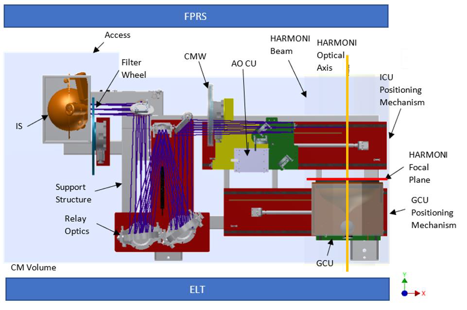
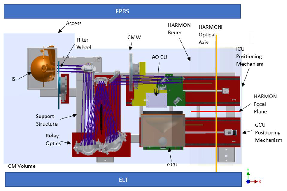
The Calibration Module subsystem (CM) is part of the CARS, Calibration and Relay System, which provides the necessary functions to deliver the telescope image to the instrument’s detectors in a calibrated form. The calibration module is the subsystem responsible for injecting the calibrated light into the system (eliminating disturbances introduced by the instrument itself), provides calibration parameters for the wavefront sensors and is located just in front of the telescope’s focal plane.
The wide range of different calibration needs of the instrument systems makes it necessary for the subsystem to be divided into 3 separate calibration units, each with a different functionality:
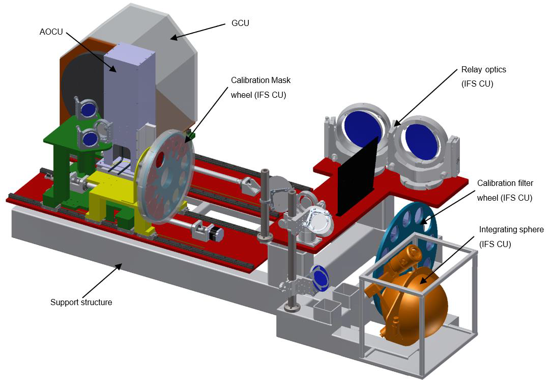
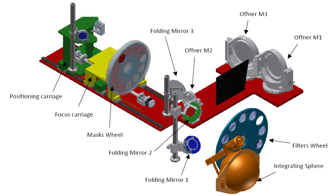
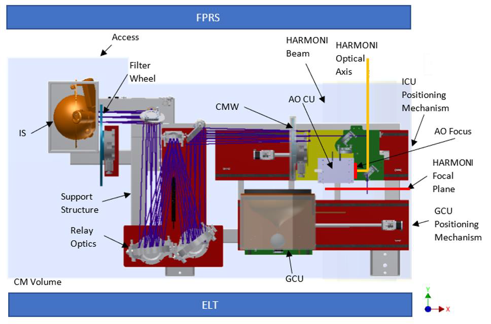
1) IFS Calibration Unit (ICU)
Calibration unit for the integral field spectrograph, which provides scientific calibrations. This unit imitates the light beam delivered by the telescope to the instrument and delivers the range of continuous and discrete sources necessary for this calibration. It includes the following components:
- Integrating sphere (IS), which provides a uniform light output.
- Continuous and discrete light sources.
- Filters Wheel, a set of equalizing filters to homogenize the spectral signal at the output of the integrating sphere.
- Relay Optics, composed of an Offner (arrangement of a set of 3 spherical mirrors) and three bending mirrors. It allows the integrating sphere and light sources to be positioned in an accessible location.
- Calibration Masks Wheel, a collection of calibration masks located in the focal plane with known spatial patterns.
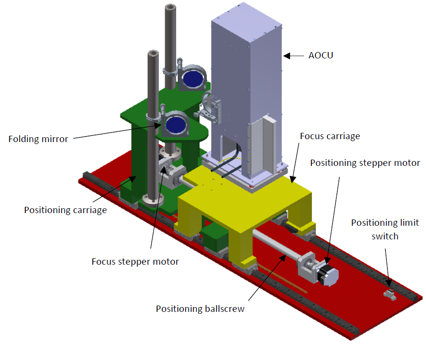
- Positioning and focus mechanisms. Two mobile carriages that enable the placement of the mask wheel in the focal plane and control its focus.
2) Adaptive Optics Calibration Unit (AOCU)
This device provides the necessary devices for calibrating high-order adaptive optics wavefront sensors and allows for the measurement of non-common path aberrations (NCPA) between the SCAO wavefront sensors and the scientific focal plane. The unit consists of the following elements:
- A deformable mirror.
- Optical transmission, consisting of a spherical collimating mirror and a ceiling mirror.
- Fiber optics.
- Monochromatic light sources.
- Bending mirror, to inject light into the instrument.
The AOCU is mounted on top of the ICU positioning mechanism, which enables control over its position and focus.
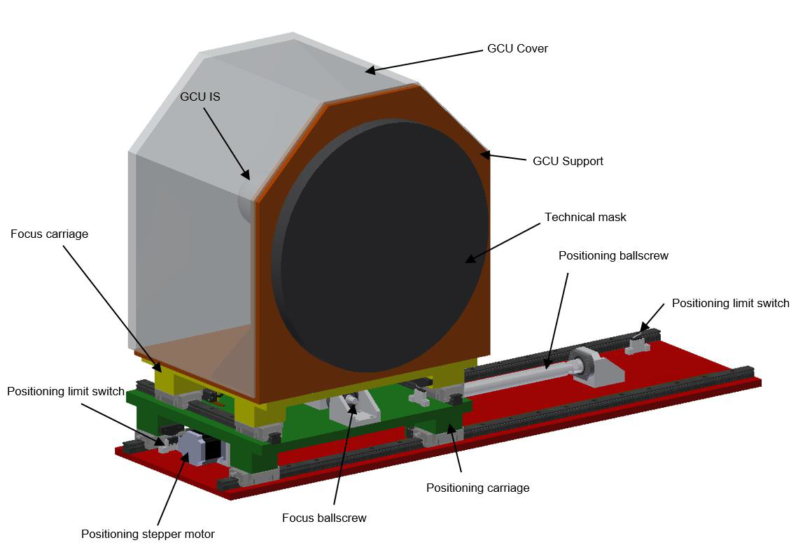
3) Geometrical Calibration Unit (GCU)
The geometric calibration unit provides a known geometric array of point sources throughout the technical field of the instrument. Thanks to this unit, the guide probes of the natural guide star sensors (NGSS) are calibrated and the pattern of distortion of the focal plane transmission can be corrected. This device implements the following components:
- Light sources (LEDs).
- Integrating sphere.
- Set of 480 fibers that transport the light from the integrating sphere to each hole in the mask.
- Technical field mask (array of 480 pin-holes).
- Positioning and focus mechanisms. Two mobile carriages that enable the placement of the mask.
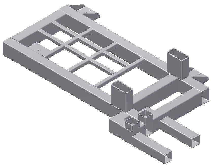
4) CM Support Structure
It is a bench that serves as mechanical support for the 3 calibration units of the subsystem and provides the mechanical interface points with the rest of the instrument through the ISS, or static structure of the instrument.
Subsystem’s Operating Modes
1) Telescope Observation
State in which the calibration module is deactivated and the light from the telescope passes directly into the instrument. No component of the subsystem shall interfere with the beam path, all devices shall be out of the way.
2) IFS Calibration
The ICU positioning and focus carriages are deployed so that the light from the integrating sphere is sent to the optical axis of the instrument.
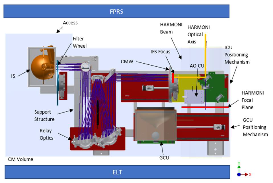
3) AO Calibration
In this mode of operation, the ICU position and focus carriages are positioned to allow light from the AOCU to be injected into the output aperture of the subsystem.
4) Geometric Calibration
Finally, if geometric calibration is required, the ICU positioning and focusing carriages are moved away from the optical path while the GCU positioning and focusing mechanisms are aligned with the optical axis of the instrument to transmit the light beams needed for calibration.