
The LOWFS Pick-Off Arm (POA) is an assembly of two rotating mechanisms in a “theta-phi” configuration inside the NGSS system. Its purpose is to patrol the telescope’s technical field accurately, to ensure image stabilisation and to transmit the light captured by the Pick-Off Mirror from the technical field to the subsystem detectors.
Due to the high precision to be achieved and all the restrictions imposed by the requirements (especially in volume, as the POA has to be very small in height) it has been necessary to study and compare different motion technologies in depth.
One of the first proposals for the secondary axis was to use stepper motors with a 5000:1 three-phase reduction gearbox. However, since the backlash of the mechanism has to be almost non-existent and the mechanism took up a lot of space, this solution was not satisfactory. Therefore, it was decided to implement a brushless motor in direct drive configuration.
To validate the electromechanical design of the POA’s secondary axis, the CAB HARMONI team has developed an engineering model of the secondary mechanism. The purpose of this prototype is to verify through numerous tests that the chosen technological solution is valid and meets the strict requirements for positioning and repeatability, which are 6.1 μm RMS and 0.8 μm RMS over distances of 3.3 mm respectively at a speed of ±2000 arcsec/s.
It is driven by a 6-pole frameless brushless motor, of 400 VAC power supply and inrunner architecture (the rotor is on the inside and the stator is on the outside). The motor is in ‘direct drive’ configuration, what means that the rotor shaft is directly coupled to the arm, without any gearbox or other mechanism. In addition, an incremental encoder with more than 30,000 lines is used to determine the angular position of the arm.
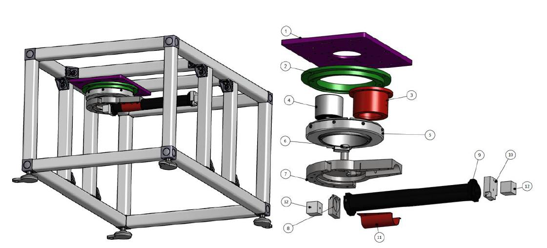
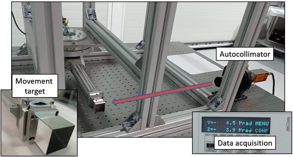
The following image shows an exploded view of the secondary axis and the structure used to support it. Also, see that cubic mirrors are placed at both ends of the arm to allow the measurement of the position of the arm with external instrumentation, instead of the bending mirrors of the actual design.
The instrument used to perform the external measurement of the arm’s position is an autocollimator, which is an optical instrument that uses the reflection of a monochromatic laser to measure small angular differences with respect to two axes with a high accuracy (below 1 μrad), but in a very small range (2000 μrad).
After many tests, the results have pleasantly surprised the team and the Consortium alike, as the response of the mechanism is very good and almost within the requirements even without using the final electronics and runnig a fully tuned control loop.
