Science capabilities
HARMONI is a versatile instrument, and the gamut of science observations it spans is correspondingly large. Primarily a single-field, medium spectral resolution, near-infrared integral field spectrograph, it is designed for detailed, spatially resolved studies of single objects that are spatially extended on scales of a few arc seconds. The lowest spectral resolving power (of ~3000) is designed to allow working “in-between” the bright night sky emission lines, while at R~7000 proper “OH-avoidance” schemes may be implemented. Utmost sensitivity is achieved by a combination of maximising throughput (signal) and minimising noise. Even with the best state-of-the-art detectors, quite a few of the spaxel scale-resolving power combinations provided by HARMONI are detector read-noise limited. Thus, the instrument design is pushed hard to maximise A-Ω product. In comparison with SINFONI, which provides 250 mas × 125 mas × 8m2, or KMOS which provides 200 mas × 200 mas × 8m2, both for 18 μm pixel detectors, HARMONI provides 60 mas × 30 mas × 39m2 with a 15 μm pixel detector, a factor of 1.77 gain over SINFONI, and 1.38 over KMOS. Spectrally, sensitivity is maximised when a line is just barely resolved – providing three different spectral resolving powers ensures that the instrument configuration always matches the source being observed.
Equally important is the “point-and-shoot” capability it provides for point-like objects. At the ~10 mas (milli-arcsecond) scales probed by the ELT, positioning a slit or a small aperture accurately on the scientific object being studied requires precise knowledge of (relative) source coordinates at a level that present-day users of 8-10 m class telescopes are not used to. Furthermore, it is often the case that the brightest regions in broad-band images do not correspond to the observed morphology in specific emission lines, thus making it impossible to position a slit. Near-infrared observations are also plagued by bright sky background (compared to the visible), so that keeping the aperture as small as possible pays hefty dividends in terms of lower background and improved signal-to-noise ratios.
Apart from its unique combination of enormous collecting area and exquisite spatial resolution (~10 mas, corresponding to ≤100 pc over a large range in redshift) over the entire near-infrared wavelength range, HARMONI also stands out in providing visible wavelength coverage. It is the only instrument within the ELT’s first generation suite to provide a visible wavelength capability, opening up parameter space crucial for new discoveries. It is also the only ELT spectrograph (even including planned second generation ELT instruments) optimised for the K-band, using a design that minimises excess thermal background. It can provide a high contrast capability, with a bespoke pupil plane apodiser that meets the goal for 106 contrast at <0.2 arcsec.

Instrument Design
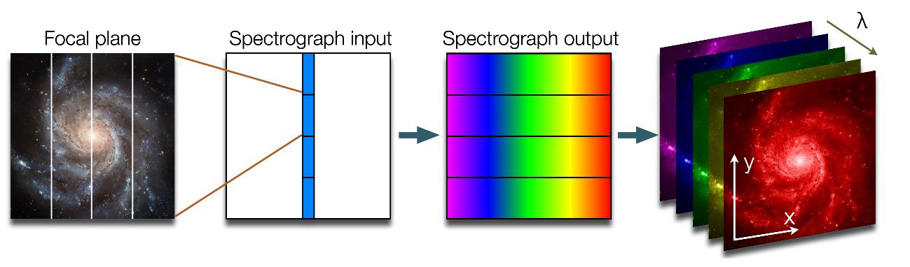
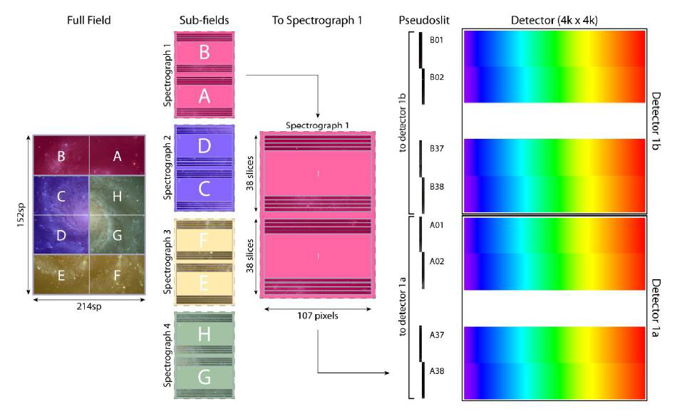
As introduced in the previous section, HARMONI is an instrument that will provide 3D spectroscopy with a wide variety of spatial and spectral settings. It will use image slicers to provide spectra over a single contiguous field of 204×152 “spaxels” (spatial pixels), approximately 31000 spectra in a single observation or data cube. The instrument will have 4 spaxel scales, 60×30, 20×20, 10×10 and 4×4 mas (milli arc-seconds), which are equivalent to fields of view on the sky of 9.1×6.1, 4.1×3.0, 2.1×1.5 and 0.84×0.63 arcseconds respectively. On the other hand, 11 spectral resolution settings of 3500, 7000 and 17000, covering the wavelength range from 0.46 to 2.45 μm (non-simultaneous), can be configured at all of the above spatial scales.
In addition to the adjustments that can be made to the field of view, spectral resolution and wavelength selection, the instrument can operate with three different adaptive optics systems (or none at all), which correct for disturbances introduced by the atmosphere (called ‘seeing’). These four modes of operation are explained later in this section.
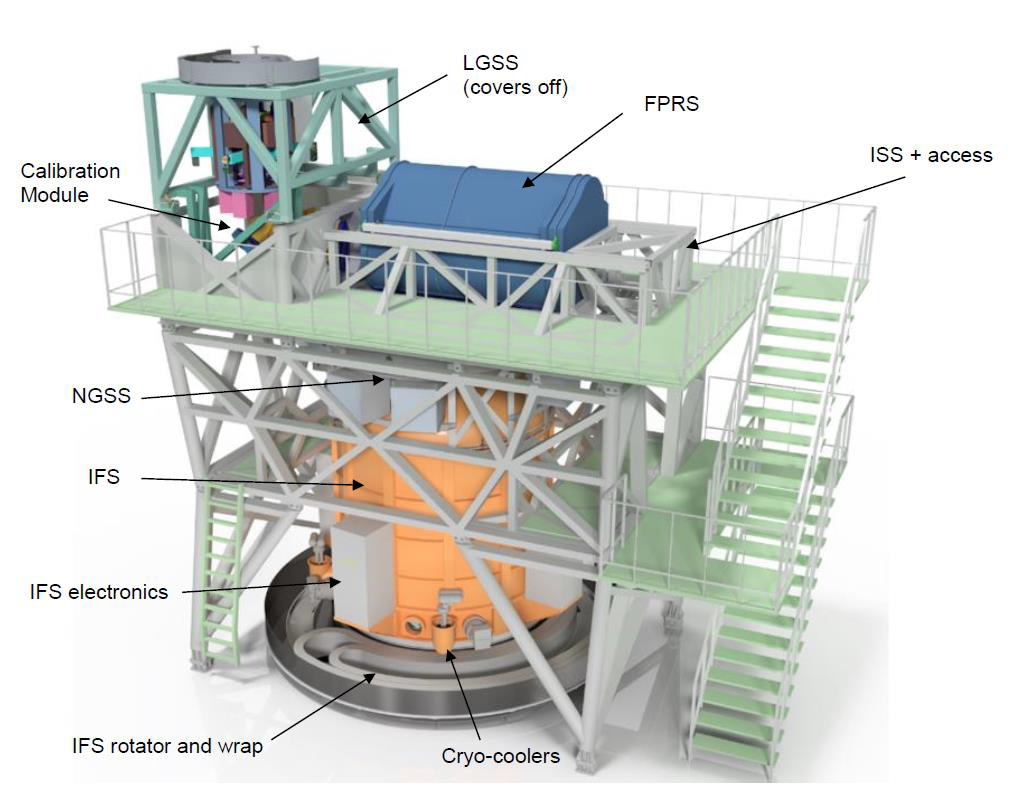
The light from the telescope is transmitted to the instrument via a cooled transmission system, to minimise thermal noise, and a dichroic in front of this system separates the LGS (laser guide star) light from the NGS (natural guide star) and scientific light to enable LTAO (one operating mode of HARMONI) observations. On the one hand, the reflected laser light is redirected to the rotating LGSS system (defined below), which contains 6 laser guide star wavefront sensors. The dichroic is removed to allow visible light spectroscopy (below 630 nm). On the other hand, the 120-second NGS/scientific field (the NGS system is defined below) from the dichroic is directed from the cooled optical transmission system to a downward-facing, vertical focus, which allows for a gravity-invariant rotating configuration of the instrument. Likewise, the instrument calibration light is fed through the dropdown Calibration Module before reaching the transmission system.
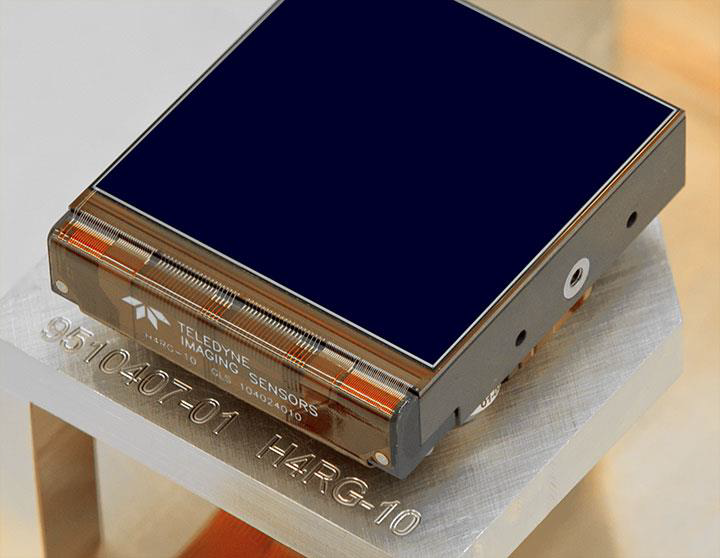
Most of the instrument’s opto-mechanical components are located in a cryostat at 130K. A pre-optics subsystem provides the selection of the 4 spatial pixel scales, as well as other beam conditioning functions such as filters and pupil masks. The rectangular field output from the pre-optics is transformed into four linear slits by the IFU (integral field unit) subsystem, and each slit is fed to one of the four spectrographs. These spectrographs collimate, scatter and focus the light on the detectors, providing the selection of spectral ranges and resolution described above. Each spectrograph has a camera for the NIR (near infrared) from 0.8 to 2.45 μm, for a total of 4, and there is a camera for the visible (VIS) from 0.46 to 0.82 μm in only 2 spectrographs. Each camera has a pair of 4K detectors and the NIR detectors are cooled to a temperature of 40K.
Outside the cryostat, a wavefront sensor of the SCAO receives light in the visible range from a deployable dichroic that covers the scientific field. A deployable module designed to pre-process the scientific light to optimise the high contrast performance of the instrument is mounted close to the SCAO dichroic. The wavefront sensors of the secondary guidance and the LTAO-NGS are mounted on two arms (POAs) that patrols the entire 120 arcsecond technical field of view. All of these wavefront detection subsystems are mounted above the cryostat, so they rotate in conjunction with the cryostat thanks to the instrument’s rotator. This rotator also provides an envelope to carry the services from the rotating section to the non-rotating facilities on the Nasmyth platform. The local control systems for the instrument and detectors are located on or near the cryostat to minimise the length of cabling.
Finally, the high-level control centre and data processing control software is located outside the instrument in a control room.
Instrument Operating Modes
HARMONI has 4 different modes of operation:
1) NoAO – No Adaptive Optics (‘seeing’ limited)
The instrument performs observations without any adaptive optics system. It only monitors the motion of the guiding sources and sends slow “secondary guidance” corrections, at a frequency of less than 1 Hz, to the telescope control system. This is the instrument’s simplest, or most traditional, mode of operation, requiring only a sufficiently bright star to perform secondary guidance.
2) SCAO – Single Conjugate Adaptive Optics
In this mode of operation, the instrument takes full control of the wavefront by detecting the higher order aberrations of a bright natural guide star (R≤16) at or very near the optical axis (center of the field). Finally, wavefront correction values are calculated and sent to the central control system (CCS) so that these corrections are applied to the telescope’s M4 and M5 deformable mirrors.
This method of operation is the best performing of the entire instrument, reaching the diffraction limit of the telescope. However, its use is very restricted by the operating conditions, because it requires a star with a very specific brightness close to the area or very specific brightness close to the area or celestial body to be observed.
3) HCAO – High Contrast Adaptive Optics
Mode of operation that is developed when an additional wavefront sensor, Zelda, is added to the SCAO mode of operation to provide detection of higher order terms not detected by the main SCAO sensor of a bright star (R≤9) on the target axis. The primary use of this mode of operation is exoplanet detection.
Note: “R” is the magnitude, an astronomical measure of the brightness of a star, at the red wavelength.
4) LTAO – Laser Tomographic Adaptive Optics
This mode of operation is set to work when the LGSS system (Laser Guide Star Sensors) is used to detect higher-order wavefront aberrations from laser guide stars projected on the sky by the telescope itself, while lower-order wavefront aberrations are detected from a faint natural guide star off-axis from the target.
The wavefront measurements are combined to estimate the optimum wavefront for the scientific field, which is sent to the CCS (Central Control System) to apply corrections to the to apply corrections to the telescope’s M4 and M5 deformable mirrors. In addition, the LTAO has two control sub-modes, “sequential” and “cascade”, both of which enable maximum throughput and the highest sky coverage depending on the availability of guide stars.
LTAO is the intermediate step between NoAO and SCAO, because if there is no star with the right characteristics for SCAO operation, lasers are used as artificial guide stars.
Functional Breakdown and Instrument Systems
The telescope is in charge of collecting the light from the observations, pointing the objects in the sky and performing the wavefront correction through the M4 and M5 mirrors. Meanwhile, HARMONI performs the detection of the wavefront errors and sends the corrections to the telescope in order to be executed and brings the light from the telescope’s science object to the cryostat detectors. It can be summarised that HARMONI is a combination of adaptive optics systems (SCAO and LTAO) and a scientific instrument (integral field spectrograph).
The instrument is divided in seven systems:
1) LGSS – Laser Guide Star Sensors
The LGSS system is located at the entrance of HARMONI. It is used to detect high order wavefront errors using six laser guide stars (LGS) for the LTAO mode of operation.
2) NGSS – Natural Guide Star Sensors
The NGSS collects all the natural guide star sensing functionality in a single place. It detects wavefront errors, including positioning and focusing of the telescope, using natural guide stars (NGS).
The NGSS supports the 4 operating modes of the instrument (explained further below): SCAOS, in the subsystem of the same name; HCAO, in the HCM subsystem; and LTAO and NoAO in the LOWFS subsystem. Also note that LOWFS includes secondary guiding for NoAO and two wavefront sensors for LTAO, all of which share a common moveable pick-off assembly.
3) CARS – Calibration and Relay System
This system is further divided into two subsystems, the FPRS (Focal Plane Relay System) and the CM (Calibration Module). The former is responsible for separating the LGS light from the science/NGS light using a dichroic and for relaying the telescope’s focal plane to a position suitable for the IFS (Integral Field Spectrograph). On the other hand, the tasks of the calibration module are to provide spatial and spectral calibration light and targets for the IFS and NGSS and to calibrate the adaptive optics sensors. In addition, the system provides a protected and controlled environment for the instrument components, shielding them from dust, light, outside temperature, etc.
4) IFS – Integral Field Spectrograph
The spectrograph obtains a spectrum of every point in a continuous field, providing a selection of image scales, resolutions and spectral ranges. It also blocks excess thermal radiation outside the telescope pupil and excess light outside the scientific field. It rotates with the field or with the pupil and is located inside the large cryostat of the instrument at very low temperatures.
This system is the heart of the instrument, as it is where all the scientific instrumentation is located, notably the IFU, the spectrographs and the scientific detectors.
5) HCS – Harmoni Control System
This instrument system provides telescope users the ability to control and monitor functions of the other systems (LGSS, NGSS, IFS and CARS); it collects observation data and sends them to a file, and also enables wavefront control by calculating the error and making corrections.
The HCS system is divided into 3 sub-systems: ICE (Instrument Control Electronics), ICS (Instrument Control Software), and AOCS (Adaptive Optics Control System).
6) HSS – Harmoni Science Software
A system that provides the telescope user with tools and programs for estimating performance, defining the observations to be made and allowing astronomers to convert the raw observational data into useful information through data reduction software.
7) SSE – System Support Equipment
It provides the instrument specific equipment necessary to integrate, test, ship, install and maintain the instrument.